 You will need at least two tools (and probably 3 or more) to create your 3DO
files:
You will need at least two tools (and probably 3 or more) to create your 3DO
files:Last updated: 12/28/98 21:57
 You will need at least two tools (and probably 3 or more) to create your 3DO
files:
A 3D rendering program
The rendering program is what you will
use to create the different "pieces" of your unit in 3D. Each piece will
then be saved as a DXF or LWO file. The problem with this step in the unit creation
process is that very few people have a 3D rendering program! Quite a few
people have latched onto a tool called Rhinoceros
because it is, for the time being, free! Other tools include 3D Studio MAX.
(9/10/98) I have added an additional web page titled Rhino/TA Editing Tips to give a few additional tips for using Rhino to do your 3D modelling.
Some miscellaneous tools
Such as Breeze, Quadface, Soap, and Visual
Soap exist to "clean up" the shapes that are exported by some rendering
programs. You can find some of them at Fileuniverse. At this point, I don't know what that means, but I
assume that you'll find out when you get to this step.
Kinboat's 3DOBuilder
application
This tool will import the DXF or LWO files you created with
your 3D rendering program, assign child/sibling relationships between the pieces, and add
the textures to the various faces of the pieces.
Kinboat's 3DOBuilder is available in both a normal version, as well as another version that includes additional Visual Basic modules (if you need them). After installing the program, view the tutorial.doc file that is installed in the same directory for a little tutorial.
The final model for your unit must be given the name unitname.3do, where "unitname" is the short name for your unit. The corpse should follow the naming conventions and have the name unitname_dead.3do. Both files will be placed in the unit's objects3d directory. Note you can, if you wish, have several different types of corpses for a single unit, or you can have no corpses at all (as is the case with most aircraft).
The most easily accessible rendering program currently avaialble is called Rhinoceros, and is currently downloadable for free. Since it's free, and it's the only one I've used, I'll use it through these examples.
Essentially, you are going to create your model in 3D space, and export the objects you create in "AutoCAD DXF" format. I'm not going to go into the details of how to use Rhinoceros. Let's just say that it can be as complicated as you want it to be, and you can read the tutorials and instruction manuals that you can download from their web site.
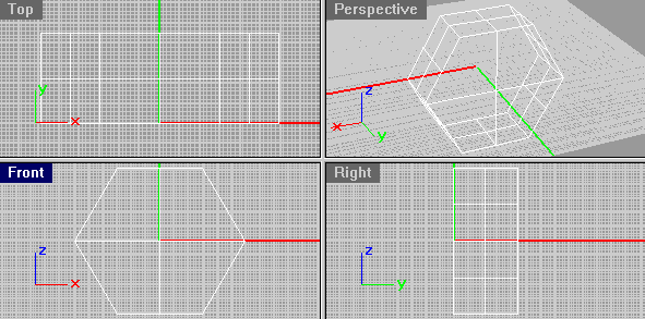 Keep in mind when creating your units, that to Total
Annihilation, the Y-Axis is "Up". This means that the
"Front' view in Rhinoceros is actually a top view of the model, with the Front
of the model at the bottom of the window (the front is the positive
Z-Axis). This is important, because above all else, you need to remember which way
is up, and which way is front.
Each model you create is a single piece of your final TA unit. This means that you have to build each base, turret, arm, etc., individually, then use 3DOBuilder to combine them all into the final model. You can, however, reuse a single model (such as a turret), and use several copies of the same piece to create multiplie pieces (such as the 3 turrets on the ARM Millenium battleship's front gun).
When building your model, keep in mind the size of the unit you are creating so that you don't create a mini-Kbot the size of a Krogoth, or a Fusion Plant the size of a Pee-Wee. A few unit sizes for reference are:
| Unit | X-Axis (Width) | Z-Axis (Depth) | Y-Axis (Height) |
|---|---|---|---|
| Core Hellfire (Big-Ass Tank) | ~44 | ~55 | ~50 |
| Core Fink (Scout Plane) | ~25 | ~40 | ~10 |
| Core Pyro (Flame Thrower Kbot) | ~25 | ~30 | ~30 |
The "groundplate" for a unit is many things, but you can simply think of it as (1) the footprint of the unit and (2) the little green box that is drawn around your unit when you select it. It can be easily created right in 3DO Builder.
(12/20/98) Here is a note I received from Jonathan Bastow concerning an issue. Sometimes your unit might do all kind of bellyflops and flips when it hits uneven terrain. Here is what he discovered: "Well, I had to dig through the last 100 days of posts on a ta editing site, but I think I found the asnwer (well, my little Katyushka drives correctly now). Evidently if your groundplane is the wrong way up your vehicle goes nuts on slopes. I flipped mine over and the little guy worked fine. If you ever start some sort of 'troubleshooting' section on your page you might want to add that as it has got to be the least intuitive bug fix I've ever encountered..."
Each part should be defined keeping in mind where the origin (point 0,0,0) lies with respect to the piece. This is because you will have to remember where the pieces "origin" is in the final model to know how it is going to behave when you tell a piece to do something like "rotate around your X-Axis").
 Once you
have created your 3D model, the last step is to "Explode" the model into the
individual faces (called "surfaces" in Rhino) that wil be used by 3DOBuilder to
assign the textures to each face. You do this by selecting your 3D object and
choosing Edit->Explode from the menu bar at the top of the screen.
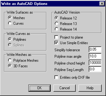
Because Rhinoceros works with its own filetype, you will want to make sure you save your model as an "AutoCAD DXF" file. When saving your model, you can/should leave most of the values at their default setting. It is important, however, to write Surfaces as Meshes, Curves as Polylines, and Meshes as 3D Faces. Choose AutoCAD Release 12 (or 14, but 12 is recommended), and click "OK" to save the model.
This just in: I just learned that Rhino supports saving in a Lightwave (LWO) file format. Apparently, if you save your exploded model as a LWO file, you will not encounter the "extra lines" problem associated with DXF files. Therefore, if you choose to save your exploded model as an LWO file, you will be able to skip the next step (Cleanup), and move directly to the "Building the Model" phase. However - I noticed that if you export your model in LWO format, the orientations of "up" and "down" are reversed. If you plan on using the LWO method, the "Top" window in Rhino (which we know now to be the side view) is upside-down!
 Note:
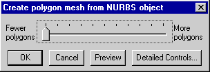
Whenever possible, you want Rhino to create as few Polygon Meshes as possible (especially
for simple, square-ish shapes) to reduce the amount of effort it takes to add texture, and
to simplify the CPU processing needed to work with your unit. When asked the
question "Create polygon mesh from NURBS object", move the slider to the lowest
setting possible before saving your model piece. Rhino tries to break your surfaces
into 3 or 4-sided surfaces, and it may not break up the shapes in a way that you'd expect,
so it's a good idea to try to create your unit out of simple 4-sided shapes to begin with.
Some info from Red MaX (Christian Deibler): "Rhino3D is a NURBS-model renderer. What that essentially means for us is that the types of objects created and how they are constructed differ significantly from a deformation-based modeller, such as 3DSMax. When you make surfaces and solids in Rhino, you are creating TrueSpace objects, which are handled very differently from three dimensional faces, which is what we need. The reason that Rhino goes through all of those dialogs when you export to an AutoCAD DXF or Lightwave file is that there must translation from TrueSpace to 3DFaces, and this requires "exploding" your pretty model."
 The next step is very simple if you simply avoid asking the question
"Why?". Why? I don't know myself, but this works.
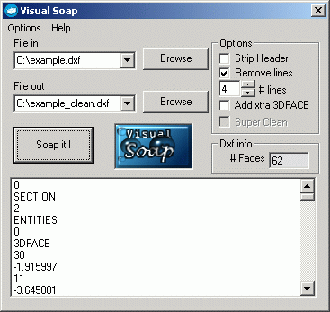
The DXF file that is generated by Rhinoceros is almost what you really want. To get what you really want, you'll have to use a tool like Visual Soap. Simply put, you need to use Visual Soap to "Remove 4 Lines" from your DXF file. What 4 lines? I dunno, just shut up and do this and you'll be fine.
Download Visual Soap, install it, and run it. Type in the name of the file you want to "clean up", type in the name of the output file, and check the box to "Remove lines" and set the number of lines to 4. (Note: If you saved your DXF file as a Release 14 AutoCAD Version file, you'll want to remove 8 lines). Finally, click on the "Soap it!" button. You'll get very little feedback as to whether or not it did anything, but it should work just fine.
Once again, I'm not going to go into the level of detail on exactly how to use 3DOBuilder. I'm only going to touch on the parts that are a little sticky to get through.
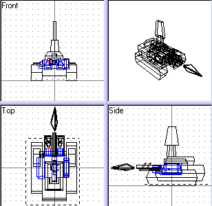
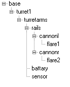 When the unit is constructed in 3DOBuilder, each piece is placed in some
child/sibling relationship to the other pieces. In a nutshell, this means that if a
parent piece (such as the base of a tank) moves or rotates, it's child pieces (such as a
tank's turrets) will move right along with them. (For a guide about child/sibling
relationship have a look at the 3DO builder tutorial ). As an example, take a peek
at the child/sibling tree to the left for the Core Hellfire to see how movements are
possible such as the way raising the turret arms (piece "turretarms") causes all
child objects (such as the rails, cannons, and even the gun-fire flares) to rise right
along with it. (And for now, we'll forgive them for misspelling the word
"battery").
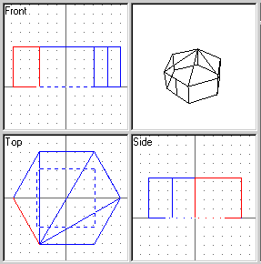 So far so
good, right? Well, even with these simple steps, something is bound to go
wrong. What could go wrong? Well, each face (or surface) on your piece model
is a one-sided face, and odds are that not all of them will be facing outside like you
want them to. And the kicker of all this is that you will be able to see which face
is inverted (because you won't be able to see it in the Unit Viewer), but you'll have to
find that face by trial-and-error. Since a final 3DO model can have many pieces,
each with many faces, it is probably easiest to create a new 3DO model with 3DOBuilder,
import only your new piece, fix it up, then export it from 3DOBuilder into yet another
cleaned (but now final) model piece. This is also a good time/place to assign the
textures to each of the faces.
From a new model in 3DOBuilder, choose File->Import Model to bring
in your new piece model. At first, you will not be able to see your 3D view in the
upper-right viewport. Assign all your faces textures, and use the F5 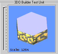 (Unit Viewer)
option to look at your model. Through trial-and-error, try to figure out which faces
are inverted, and choose the Special->Invert Face menu item to flip it
around. After locating all your inverted faces, you can then finish assigning each
face the final texture you want to give it, then export the piece as a new, corrected DXF
file for your final model.
One important note to make here: In the 3DOBuilder's "Top" view, up is the front of the unit.
When all your pieces are ready, choose the location in the model's hierarchy where you are going to insert the piece that you've rendered, exploded, cleaned, and fixed up. Choose File->Import Model from the menu bar, and select your cleaned-up DXF file. Your new piece will be placed into the model. You will use 3DOBuilder to position each piece in relation to the other pieces, and through the process, assign the child/sibling relationships between each piece.
Save your final 3DO model in the objects3d subdirectory.
(12/28/98) Note: If you encounter strange crashes in 3DO Builder coming from a file called RENDERER.DLL, disable the OpenGL view. This seems to clear up most problems people have. Thanks to The Raptor for this advice.
For people wanting an in-depth specification of the actual file format, you can view this document: